

We’re excited to share that we construct a good contact sensor swap module, made to carry fashionable options to your merchandise or units with out the hefty price ticket.
Why We Made It?
Contact swap modules are gaining recognition as a result of they use a contact sensor swap, eliminating the necessity for mechanical elements.
Plus, they will work behind supplies, offering a glossy and fashionable end to product designs.
The Value Dilemma in Contact Change Programs:
Designing programs with contact switches typically will increase the general Invoice of Supplies (BOM) price. To maintain merchandise inexpensive, design engineers generally resort to utilizing tactile switches, that are priced at 10 to fifteen rupees in SMD.
Nevertheless, this compromises the product’s aesthetics, making it look outdated. The engineers could even want so as to add a gap or reduce a mark on the product to entry the tactile push swap.
Our Resolution – A Value-Efficient Contact Sensor:
Right now, we current a contact sensor that prices round 10 rupees and works from behind supplies. You possibly can discreetly place the sensor behind any conductive materials on the physique.
Once you contact it, the sensor senses it. The fantastic thing about this design is its programmability in 4 other ways.
How It Works?
The circuit offered will be built-in into your product design. Alternatively, you may obtain the design and use it as a standalone sensor module. Improve your product’s consumer expertise with out breaking the financial institution!
Prepared so as to add a contact of innovation to your product? Let’s study step-by-step, how one can make your individual contact sensor at simply Rs. 10!
The fabric used within the challenge is listed within the desk under.
Invoice of Materials

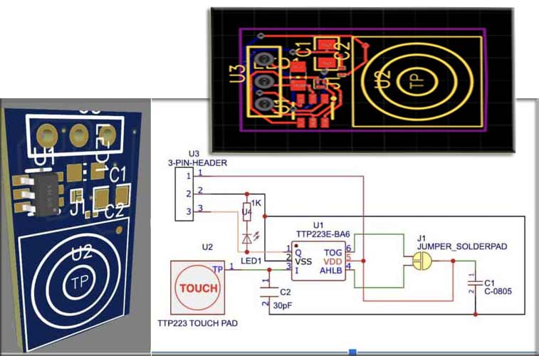
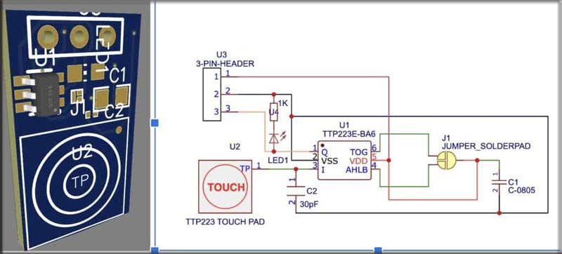
Contact Sensor Change – Circuit Design
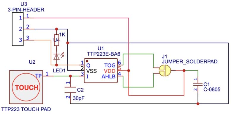
The circuit diagram of the DIY Contact Sensor Change is simple to construct.
You possibly can join the elements in keeping with the circuit diagram, we’ve got offered within the determine under and your contact sensor is prepared.
You possibly can both combine our circuit into your machine design by downloading the Gerber file or design your individual sensor module and use it for various functions.
Contact Sensor IC
In response to the datasheet, the Contact sensor IC TTP223 has the next pinout.
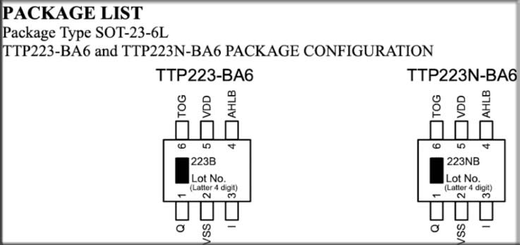
In response to the datasheet of the IC, the working voltage for the TTP223-BA6 sometimes ranges from 2.0V to five.5V and requires a sensing electrode for contact detection.
This is usually a piece of conductive materials (e.g. a chunk of copper or a conductive pad) related to the suitable pin on the IC. The TTP223-BA6 offers an output sign that modifications when a contact is detected.
You’ll want to attach this output to your microcontroller or the load you need to management primarily based on contact.
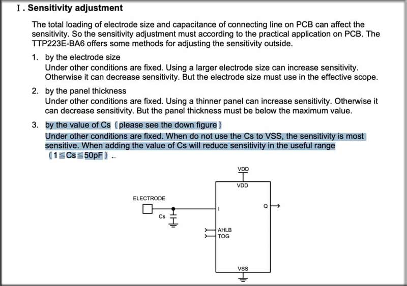
In response to the IC datasheet, the IC sensitivity impact with electrode dimension and connecting strains on PCB. The sensitivity of those will be calibrated and adjusted as per requirement utilizing the capacitor on the electrode pin “I” and GND.
The worth of the capacitor for adjustment will be vary from 1pF to 50 pF. you may seek advice from the datasheet for extra particulars.
IC Working Modes
The IC working will be programmed in 4 other ways by including a solder jumper to TOG pin 6 and Pin 4.
It offers 4 totally different choices for the habits of the Q (CMOS output) pin primarily based on the TOG and AHLB settings.
1. Push Mode:
- TOG = 0 (Direct output)AHLB = 0 (CMOS energetic excessive)
On this mode, the Q output straight follows the contact standing. When a contact is detected, the Q output turns into energetic excessive (1), and it goes again to inactive (0) when the contact is launched. That is typically used for momentary touch-sensitive purposes like buttons.
2. Toggle Mode:
- TOG = 1 (Toggle output)AHLB = 0 (CMOS energetic excessive)
In toggle mode, the Q output toggles its state with every contact occasion. Once you first contact the sensor, the output goes to energetic excessive (1), and whenever you launch the contact, it stays excessive. Subsequent touches will toggle the output between excessive and low states.
It may be used for purposes the place you need to toggle a state or swap one thing with every contact, reminiscent of a light-weight swap.
3. Toggle Mode with Energy-On State = 0:
- TOG = 1 (Toggle output)AHLB = 1 (CMOS energetic low)
Much like the earlier toggle mode, this mode toggles the output with every contact occasion. Nevertheless, when the IC is powered on, the Q output begins in an energetic low state (0). Subsequent touches will toggle the output between high and low states.
This can be utilized for purposes the place you need a explicit default state when the IC powers on, after which toggle the state with every contact.
4. Toggle Mode with Energy-On State = 1:
- TOG = 1 (Toggle output)AHLB = 1 (CMOS energetic low)
This mode is similar because the earlier toggle mode with the one distinction being that when the IC powers on, the Q output begins in an energetic excessive state (1). Subsequent touches will toggle the output between excessive and low states.
This mode can be helpful whenever you need a particular default state when the IC powers on after which toggle the state with every contact.
So you should use the solder jumper of the solder jumper pad in between these pins to vary the mode.
You possibly can join the elements in keeping with the circuit diagram, we’ve got offered within the determine under and your contact sensor is prepared.
You possibly can both combine my circuit into your machine design by downloading the Gerber file or design your individual sensor module and use it for various functions.

You may also verify our different Contact Change Tasks that we construct beforehand like Easy Contact Delicate Change, Contact Switchboard Circuit.
Testing and Gerber File
After connecting the elements primarily based on the circuit diagram, proceed to attach the solder jumper in keeping with the specified pin perform.
Now, hyperlink the LED to the output pin, and upon touching the electrode, the LED will illuminate. Discover the Gerber file for the PCB connected under.